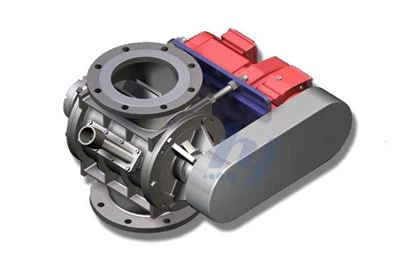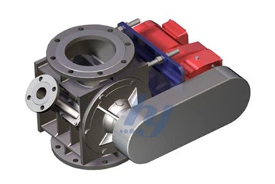

In conveying systems for powder, granular and other bulk materials, diverter valves switch materials from a single inlet to different outlets. They are vital components connecting silos, conveying pipelines, packaging lines and production equipment.
Once a diverter valve suffers jamming, leakage, incomplete switching or incorrect material diversion, it will not only interrupt material conveyance, but also trigger material cross-contamination, dust emission, product contamination, equipment shutdown and other issues. Valve failures do not always originate from the valve body itself; compressed air supply, control systems, upstream and downstream pipelines, as well as material conditions can all affect its operation.
Therefore, when handling diverter valve faults, simply replacing seals or actuators is insufficient. Instead, troubleshooting shall be carried out step by step from mechanical structure, pneumatic system, electrical control and conveying working conditions based on specific fault phenomena.
I. Diverter Valve Fails to Switch or Moves Slowly
It is a common fault in actual production that the diverter valve receives a switching command but fails to actuate, or moves at an obviously reduced speed.
Common Causes
First, check whether the compressed air meets the operating pressure required by the actuator. Insufficient air source pressure, leaking air supply pipelines, clogged filters or faulty solenoid valves may result in insufficient thrust output from the cylinder.
Second, materials may enter the movable clearances around spools, flaps or rotors and cause mechanical jamming. This problem occurs more easily with highly hygroscopic, agglomeration-prone materials or materials containing large particles.
In addition, aging cylinder seals, bent transmission shafts, damaged bearings, loose connecting parts and deformed valve bodies caused by improper installation will increase movement resistance.
Solutions
Before maintenance, stop material conveyance, cut off power and air supply, release internal pipeline pressure, and prevent accidental startup of equipment. Equipment manufacturers generally require energy isolation to be completed before disassembly, cleaning or inspection.
After finishing safety isolation, troubleshoot in the following order:
- Check air source pressure, air supply pipelines and air treatment units;
- Verify whether solenoid valves are powered on and perform normal commutation;
- Conduct switching tests under no-material conditions;
- Inspect the interior of the valve for accumulated materials or foreign objects;
- Examine cylinders, transmission shafts, connecting fittings and bearings;
- Confirm that the valve body bears no additional tensile or extrusion force after being connected to pipelines.
If the valve still moves sluggishly after removing accumulated materials, further check whether spools, flaps or rotors are worn or deformed.

II. Incomplete Switching or Frequent Position Alarms of Diverter Valve
The valve can actuate but cannot fully reach the designated position, the control system continuously displays incomplete switching, or the equipment retries switching repeatedly.
Common Causes
Such faults are usually related to mechanical travel and position detection, including:
- Materials trapped between spools and sealing surfaces;
- Displaced limit switches;
- Sensor surfaces covered by dust;
- Insufficient cylinder stroke;
- Loose transmission connecting parts;
- Offset spools caused by wear;
- Insufficient switching time reserved in control programs.
If switching is executed while materials are still flowing rapidly through the valve, particles are likely to be clamped between sealing surfaces and moving parts, making the valve unable to fully reach the target position.
Solutions
First observe the actual position of the valve to confirm whether the valve fails to move into place, or the position sensor cannot feed back signals correctly. Do not judge that the mechanical structure of the valve is damaged merely based on control system alarms.
After cleaning internal accumulated materials, readjust limit switches or proximity sensors, check the actual cylinder stroke, and confirm no looseness in transmission mechanisms. If the fault occurs frequently, review the control logic and arrange switching operations when material flow decreases or conveyance is temporarily suspended.
For systems where switching with material flow is unavoidable, select valve structures adapted to corresponding working conditions and adopt anti-trapping designs for sealing surfaces and switching components.
III. Dust Leakage at Valve Body or Connection Points
Dust appearing around the diverter valve, material leakage at valve shafts or pipeline joints will not only cause material loss, but also damage the on-site environment and threaten production safety.
Common Causes
Dust leakage may occur at multiple positions:
- Worn seals between spools and valve seats;
- Aging shaft end seals;
- Damaged flange gaskets;
- Loose connecting bolts;
- Material deposits on sealing surfaces;
- Eroded valve bodies and internal parts;
- System pressure exceeding the allowable range of the valve;
- Deformed valve bodies caused by deviation in pipeline installation.
When conveying high-hardness, sharp-edged particles or highly abrasive powder for a long time, materials will continuously scour valve channels, outlets and sealing areas. Particle hardness, shape, size, flow velocity and impact angle will all affect the wear rate.
Solutions
First confirm the specific leakage position before determining handling methods. For flange leakage, check gaskets, bolt tightening status and pipeline alignment; for shaft end leakage, inspect shaft seals and surface abrasion of transmission shafts; for internal cross-leakage inside the valve, examine sealing rings, valve seats and rotating parts.
Simply increasing bolt tightening torque cannot solve all leakage problems; excessive tightening may instead deform the valve body or damage gaskets. If leakage is caused by excessive system pressure, inspect conveying pressure, pipeline blockages and downstream flow resistance.
IV. Material Mis-Diversion and Cross-Contamination
The diverter valve has switched to the designated position, yet part of the materials still flow into the other outlet, which may lead to cross-contamination between different raw materials, formulas or production batches.
Common Causes
Material cross-flow is usually related to the following factors:
- Poor sealing on the closed outlet side;
- Worn spools or valve seats;
- Internal valve cavities prone to material retention;
- Unpurged residual materials in pipelines before switching;
- Inconsistency between position feedback signals and actual valve position;
- Errors in control programs;
- Valve structures unsuitable for working conditions requiring strict anti-cross-contamination.
Some diverter valves retain a certain amount of residual materials after conveyance. For production processes with strict batch isolation requirements, special attention shall be paid to internal retention cavities of the valve and reliable isolation performance of closed outlets. Different diverter valve structures differ greatly in residual material control and cross-contamination prevention.
Solutions
First check whether the position indicator is consistent with the actual valve position, then inspect sealing surfaces, valve seats and rotating parts.
If cross-contamination occurs after product changeover, check whether pipelines are equipped with sufficient purging or emptying time. For food, pharmaceutical, fine chemical and multi-formula production lines, formulate clear cleaning validation procedures.
If the existing valve contains internal cavities that cannot be completely cleaned, simply increasing cleaning frequency may not resolve the problem. In this case, replace it with a valve featuring continuous flow paths, minimal retention zones or compatibility with Clean-in-Place (CIP). For hygienic-grade production, quick-disassemble or CIP-suitable structures can reduce risks of material residue and cross-contamination.
V. Frequent Blockage of Diverter Valve or Adjacent Pipelines
When material throughput drops, conveying pressure rises, or no materials flow out from downstream after the diverter valve switches, it usually indicates blockage inside the valve or adjacent pipelines.
Common Causes
Factors leading to blockage include:
- Damp and agglomerated materials;
- Particle size exceeding the allowable range of the valve;
- Fibrous or flaky materials winding around moving parts;
- Mismatch between valve flow channel caliber and conveying pipeline diameter;
- Spools failing to fully reach the target position;
- Material accumulation inside closed outlets;
- Blockage of downstream pipelines, elbows or equipment;
- Insufficient conveying air volume, flow velocity or pressure;
- Improper installation angle of the valve.
It should be noted that the blockage is not necessarily located inside the diverter valve. Blockage of downstream pipelines will also manifest as no material output from valve outlets and elevated system pressure.
For certain valve structures, closed outlets may accumulate materials when conveying air flow is insufficient, which further increases blockage risks. Therefore, the valve type must match gravity conveying or pneumatic conveying modes.
Solutions
During troubleshooting, first confirm whether the blockage occurs inside the valve or downstream pipelines. Check pressure, material flow and equipment operating status section by section to avoid disassembling the valve at the very beginning.
If blockage is caused by material agglomeration, further inspect storage conditions, material moisture content, pipeline thermal insulation and air humidity. If large particles or foreign objects enter the system, check upstream screening and impurity removal devices.
For recurring blockage faults, recheck valve caliber, internal flow channels, installation angle, material characteristics and conveying parameters, instead of only conducting manual blockage removal.
VI. Excessively Fast Wear of Seals and Internal Parts
Seals are standard wearing parts under normal conditions, yet if their replacement cycle is significantly shortened, it usually indicates improper equipment selection or abnormal operating conditions.
Common Causes
Key factors affecting wear rate include:
- High hardness and abrasiveness of materials;
- Sharp edges of particles;
- Excessively high conveying velocity;
- Direct impact of materials on sealing surfaces;
- Frequent valve switching;
- Incompatibility between sealing materials and materials or operating temperature;
- Non-concentricity of spools and valve seats;
- Long-term operation of equipment under overpressure or overtemperature conditions.
High conveying velocity increases particle impact energy and accelerates wear on valve inner walls, outlets and sealing areas. For highly abrasive materials, ordinary stainless steel may not deliver ideal service life. Hardened materials, wear-resistant liners or ceramic components shall be selected according to impact positions and wear patterns.
Solutions
Record the specific wear positions each time, rather than only recording part replacement time. Wear at different positions usually corresponds to different root causes:
Severe unilateral wear: Possibly caused by pipeline eccentricity or material impact direction;
Wear on outlet sealing surfaces: Likely induced by high-speed scouring;
Shaft end wear: May result from dust intrusion or axis offset;
Overall aging of seals: Possibly related to temperature or chemical incompatibility.
For abrasive materials, consider adding wear-resistant liners, hardened internal parts or ceramic protection rings, and optimize conveying velocity and material inlet angle within the allowable process range. Wear-resistant design does not require the entire valve body to adopt high-cost materials; it is more critical to accurately protect high-impact and high-wear positions.
VII. Abnormal Noise or Vibration During Operation
Impact noise, friction sound or continuous vibration generated during valve switching is an early warning signal of mechanical faults or abnormal conveying working conditions.
Common Causes
- Excessively fast actuation speed of the actuator;
- Improper adjustment of cylinder buffering;
- Loose transmission connecting parts;
- Friction between spools and valve body;
- Damaged bearings;
- Insufficient supports for valve body or pipelines;
- Continuous impact of high-speed particles on the valve body;
- Pressure pulsation inside pipelines;
- Misalignment between valve and pipelines during installation.
Solutions
Distinguish whether the noise originates from the actuator, valve interior or conveying pipelines.
If violent impact only occurs at the moment of switching, check cylinder speed, buffer devices and mechanical limit stops. If continuous friction sound appears during operation, shut down the equipment immediately to inspect spools, rotating shafts and bearings to prevent further damage.
If vibration comes from material conveyance, check conveying velocity, pipeline supports, elbow layout and system pressure. Vibration caused by system working conditions cannot be simply eliminated by increasing bolt tightening torque of the valve body.
VIII. Increased Material Breakage and Degradation Rate
In conveying systems for plastic pellets, food granules, feed, crystalline materials and other fragile products, diverter valves are prone to causing severe material breakage.
Common Causes
Material damage is usually related to the following factors:
- Excessively high conveying velocity;
- Sharp turns inside valve flow channels;
- Steps at joints between pipelines and valves;
- Spools failing to fully align with outlets after switching;
- Direct impact of materials on closed components;
- Shearing caused by switching with material flow;
- Undersized valve caliber.
Solutions
Inspect whether internal valve flow channels are continuous, whether the inner diameters of pipelines and valves match, and whether channels are fully aligned after switching.
For fragile particles, prioritize valve structures with smooth inner walls, gentle turning angles and minimal joint steps, and reasonably control conveying velocity. Some tubular diverter valves reduce material collision and breakage by maintaining smooth internal flow channels.
IX. Valve Jamming or Deteriorated Sealing Performance After Cleaning
In food, pharmaceutical and chemical production, diverter valves require regular water washing or chemical cleaning. Some valves suffer difficult actuation, expanded seals or internal rust after cleaning.
Common Causes
- Incomplete discharge of cleaning liquid;
- Long-term liquid accumulation inside dead corners;
- Incompatibility between sealing materials and cleaning agents;
- Unsuitable valve body material for operating environment;
- Water intrusion into bearings or actuators;
- Inadequate drying after cleaning;
- Equipment not designed for Clean-in-Place (CIP) requirements.
Solutions
Before cleaning, confirm whether valve bodies, seals and lubricating materials can withstand corresponding temperature, concentration and cleaning media.
After cleaning, fully drain residual liquid and dry thoroughly, and inspect drain outlets, shaft seals and internal low points. For production lines requiring frequent wet cleaning, clarify CIP requirements during model selection. Ordinary industrial diverter valves shall not be directly applied to high-hygiene wet cleaning working conditions.
X. Correct Diverter Valve Mis-Diversion Despite Normal Electrical Control
The valve operates mechanically normally yet diverts materials to incorrect silos or production lines; such faults are more severe than ordinary shutdown failures.
Common Causes
- Incorrect wiring of solenoid valves;
- Reversed connection of two position feedback signals;
- Inconsistent outlet numbers set in the control system with on-site layout;
- Wrong air pipe connection after maintenance;
- Failure to restore automatic mode after manual operation;
- Malfunction of limit switches;
- Lack of position confirmation and interlock logic in control programs.
Solutions
After maintenance or actuator replacement, conduct no-load direction verification to ensure full consistency among control screen display, valve position and actual outlet direction.
Before automatic conveyance, the control system shall confirm target position feedback first, then allow upstream equipment to feed materials. Do not send switching commands without verifying whether the valve is fully in place.
For multi-silo, multi-formula or continuous production systems, set interlock relations among valve position, target silo status and upstream feeding equipment to reduce risks of batch contamination caused by mis-diversion.
XI. Standard Troubleshooting Sequence for Diverter Valve Faults
Follow the below inspection sequence when handling diverter valve faults:
Step 1: Confirm Fault Phenomenon
Clarify whether the fault is failure to actuate, slow movement, incomplete positioning, leakage, blockage, cross-contamination or abnormal control signals. Different phenomena correspond to different troubleshooting directions.
Step 2: Inspect Upstream and Downstream Systems
Check whether upstream feeding is still in progress, whether downstream pipelines are blocked, and whether system pressure is normal, to avoid misjudging pipeline faults as valve failures.
Step 3: Inspect Control and Air Supply Systems
Verify power supply, control signals, solenoid valves, compressed air and position feedback signals.
Step 4: Conduct No-Load Test
After clearing materials and completing safety isolation, test whether the valve moves smoothly mechanically, to distinguish faults induced by materials from mechanical failures.
Step 5: Inspect Internal Components
Focus on checking spools, flaps, rotors, valve seats, seals, rotating shafts and bearings for accumulated materials, wear or deformation.
Step 6: Verification After Restoration
After maintenance, perform both no-load and material-carrying tests to confirm normal switching position, sealing performance, conveying flow and control feedback.
Step 7: Record Fault Root Cause
Record material type, operating duration, fault location, wear status and replaced parts, which helps judge whether the fault is accidental or caused by improper model selection and process design.
XII. How to Reduce Diverter Valve Faults Through Maintenance
The inspection cycle of diverter valves cannot be fully set by fixed time intervals; it shall be adjusted according to material abrasiveness, switching frequency, conveying pressure and production environment. Basic maintenance items are listed as follows:
| Inspection Item | Main Content |
|---|---|
| Daily Patrol Inspection | Check leakage, abnormal noise, vibration, actuation time and position feedback |
| Periodic Inspection | Inspect air supply, solenoid valves, cylinders, connecting fittings and limit switches |
| Internal Inspection | Check accumulated materials, seal wear and valve body erosion |
| Cleaning Maintenance | Remove residual materials to prevent material moisture absorption, agglomeration and cross-batch contamination |
| Scheduled Overhaul | Inspect rotating shafts, bearings, valve seats and wear-resistant parts, replace components when necessary |
| Operation Logging | Record switching times, fault frequency, service life of parts and material changes |
For highly abrasive materials, arrange inspections based on wear trends instead of waiting until valve leakage or spool failure occurs. For food and pharmaceutical production, simultaneously record cleaning effects, residual material status and seal material conditions.
XIII. When to Repair and When to Replace a Diverter Valve
Damaged seals, solenoid valves, cylinders and position sensors can usually be restored by component replacement.
However, valve replacement or re-selection shall be considered under the following circumstances:
- Valve body severely perforated or deformed by erosion;
- Spools and valve seats unable to restore effective sealing after repair;
- Recurring frequent faults leading to continuous increase in maintenance costs;
- Mismatch between valve caliber and actual conveying capacity;
- Existing structure failing to meet anti-cross-contamination requirements;
- Valve incompatible with current material temperature, abrasiveness or corrosiveness;
- New hygiene cleaning or explosion-proof requirements added to production lines;
- Significant changes in system working conditions.
Repeated seal replacement cannot resolve problems caused by improper structural selection. Only by comprehensively matching material characteristics, conveying mode, pressure, temperature, installation direction and cleaning requirements can fundamental fault reduction be achieved.
Conclusion
Diverter valve faults are usually induced by multiple factors. Material jamming may relate to damp materials, seal leakage may stem from abnormal wear, incomplete switching may be caused by air supply, sensors or control programs, and mis-diversion may result from on-site wiring and interlock logic errors.
When handling faults, confirm the specific phenomenon first, then inspect upstream and downstream working conditions, pneumatic systems, electrical control and mechanical structures in sequence. For recurring faults, re-evaluate whether the valve type, material, sealing design and conveying parameters truly match the current production conditions.
Only by combining proper model selection, standardized installation, regular inspection and preventive maintenance can the service life of diverter valves be extended, downtime reduced, and stable operation of powder and bulk material conveying systems guaranteed.
Match Diverter Valves to Your Conveying System Better
Different powder and granular materials vary greatly in fluidity, abrasiveness, temperature, humidity and cleaning requirements. When selecting diverter valves, comprehensively judge based on conveying mode, operating pressure, material characteristics, number of outlets and anti-cross-contamination standards.
HANYE can provide customized solutions including diverter valve model selection, structural design and material configuration according to your production working conditions, helping reduce blockage, leakage and abnormal wear, and improve the stability and maintenance efficiency of material conveying systems.
Please contact our team immediately.